Single Phase Energy Meter Phasor Diagram
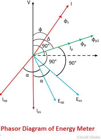
What Is Energy Meter Definition Construction Working Theory Circuit Globe

Three Phase Transformer Connections Phasor Diagrams Transformers Connection Diagram

Diagram Single Phase Phasor Diagram Full Version Hd Quality Phasor Diagram Chartdiagram Lineakebap It
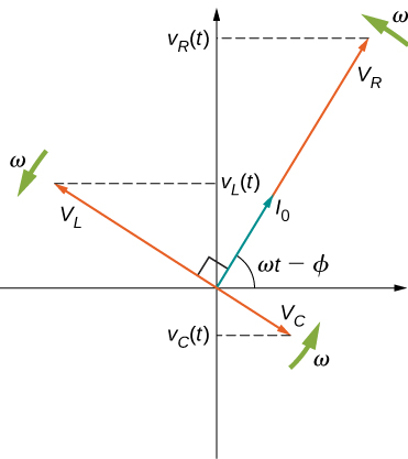
15 4 Rlc Series Circuits With Ac Physics Libretexts
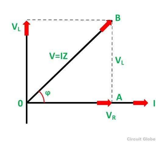
What Is Rl Series Circuit Phasor Diagram Power Curve Circuit Globe
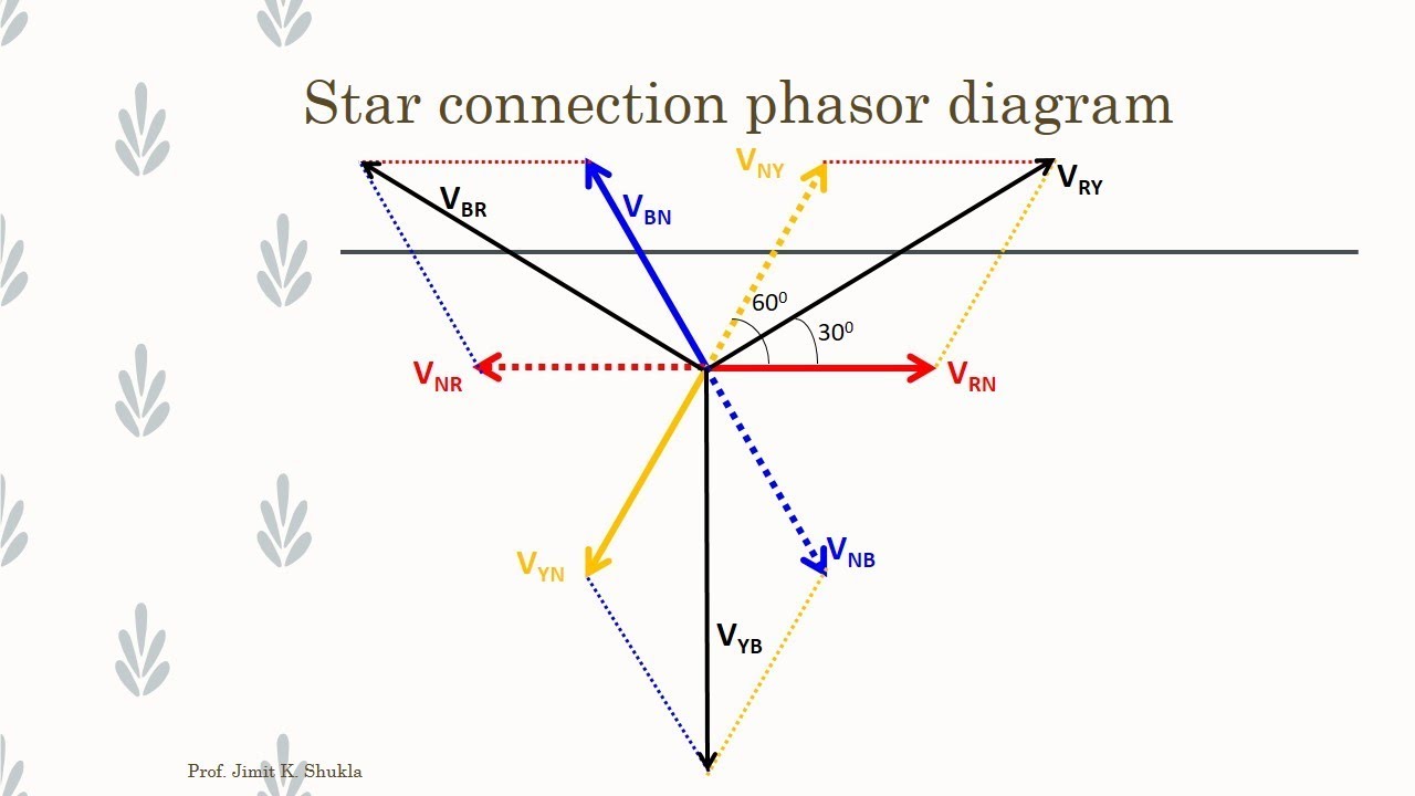
Diagram Electrical Phasor Diagram Full Version Hd Quality Phasor Diagram Chartdiagram Lineakebap It
Theory operation working 5.
Single phase energy meter phasor diagram.

Phasor Diagram For The Interfering Fields Top And The Resulting Power Download Scientific Diagram
Gps Signal Phasor Diagram Describing Carrier Tracking Loop Operation Download Scientific Diagram
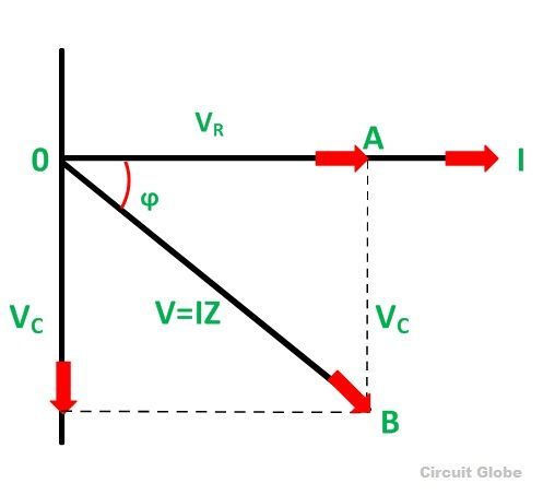
What Is Rc Series Circuit Phasor Diagram And Power Curve Circuit Globe

Phasor Diagrams For Amplitude Left Panel And Phase Right Panel Download Scientific Diagram

Figure A 1 Two Axis Synchronous Machine Phasor Diagram Download Scientific Diagram

Capacitor Phasor Diagram 12 13 Download Scientific Diagram

Data Logger Power Factor Meter Power Quality Analyzer Three Phase Power Monitor

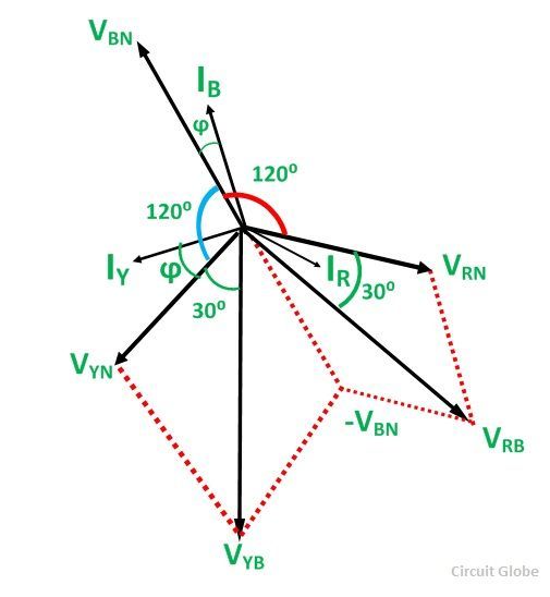
Measurement Of Reactive Power By Single Wattmeter Method Electrical Technology And Industrial Practice

1 Phasor Diagram
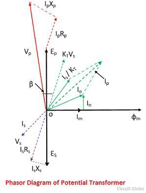
What Is Potential Transformer Pt Definition Construction Types Errors Phasor Diagram Applications Circuit Globe
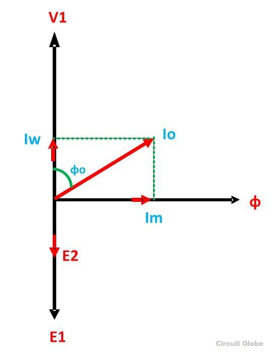
Transformer On No Load Condition Its Phasor Diagram Circuit Globe

3b Phasor Diagram For Three Wire Network With Y Connected Transformers Download Scientific Diagram

Phasor Diagram In The Complex Domain Showing The Phase Deviation Download Scientific Diagram
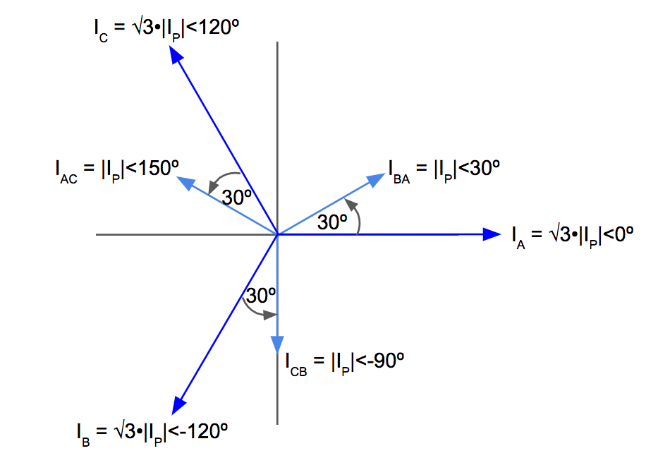
Open Delta Transformer Connection Electrical Pe Review

Analysis Of The Equivalent Circuit Induction Machines With Images Single Phase Transformer Transformer Construction Circle Diagram
Phasor Diagram Of The Cascade Ptc Figure 4 B Shows The Amplitude Download Scientific Diagram
Two Wattmeter Method Balanced Load Condition Circuit Globe

Potential Transformer Construction Working Theory Phasor Diagram Errors Characteristics
1

Nw 2263 Phasor Diagram Of Induction Motor Your Electrical Home Download Diagram
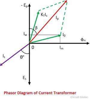
What Is Current Transformer Ct Definition Construction Phasor Diagram Types Circuit Globe
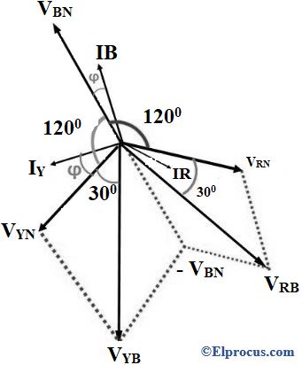
Two Wattmeter Method Construction Derivation Its Applications
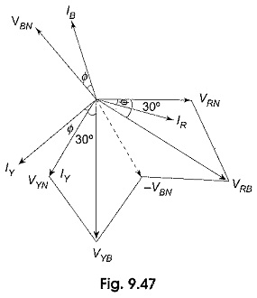
Power Factor By Two Wattmeter Method
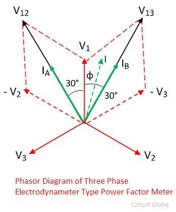
What Is Power Factor Meter Definition Types Circuit Globe
Source : pinterest.com
